Tuesday, September 4, 2012

Octave Equalizer

This Equalizer will satisfy your wishes about your sound appetizing, you can plug in your audio device or can be used as a guitar tone control. 
If you don't want your audio device looks much potensiometer control, you can change the potensiometers with trimpot and it' will hided in the equalizer box.


Schematic of Octave Equalizer

Solder side of Octave Equalizer PCB

Component Side of Octave Equalizer PCB
 Parts List :

Resistor:
R1 = 68 KOhm
R2,R6,R11,R15,R16,R17,R18,1R19,R20,R21,R22 = 1 KOhm
R3 = 6,8 KOhm
 R4,R7,R8,R9,R12,R13 =3,9 KOhm
R5,R1O = 12 KOhm
R14 = 220 KOhm
R23,R24,R25,R26,R27,R28,R29,R3O = 82 KOhm
P1...P8 = Potensiometer 10 KOhm linier

Capasitor:

C1 = 820 nF
C2,C5,C6,C9,C36 = 820 pF
C3,C7 =   100 uF/4 V
C4,C8,C24,C30 = 4,7 nF
C10 = 470 nF
C11 = 1uF
C12,C15 =  270 nF
C13,C16,C2O = 47 nF
C14,C23 =  15 nF
C17 =   12 nF
C18,C21 = 3,3 nF
C19 = 33 nF
C22 = 560 pF
C25,C34 = 1 nF
C26 = 39 pF
C27 =  560 nF
C28 =  82 nF
C29 = 27 nF
C31 = 120  nF
C32,C35 = 39 nF
C33 = 6,8 nF
C37 = 1,5 nF
C38,C41 = 470 pF  
C39 = 10 nF
C40 = 3,9 nF
C42 =  15 pF
C43,C44,C45,C46,C47,C48 = IO0 nF MKM
C49,C50 = 10 uF/25 V

Semikonduktors:
T1,T2,T5 = BC 549C/BC 550C
T3,T4,T6,T7 = BC 559C/BC 560C
IC1,IC2 = TL 084


Sunday, September 2, 2012

Super Headphone Amplifier

Output Illustration
Spec. of Super Headphone Amp.

Output (in Class A) :
160mW at 8  Ohm
600mW at 30 Ohm
120mW at 600 Ohm

Distortion :
Less Than 0.01% at Normal Outout


Schematic
PCB1
PCB2

Parts List :

Reslstor :
R1,R1',R4,R5,R18,R18' = 1 k
R2.R2',R9,R9',R17,R17' = 22 k
R3,R6 = 27 k
R7,R7' = 220 k
R8,R8',R19,R19' =2k2
R10,R10',R13,R13' = 4k7
R14,R14',R20,R20' = 330 Ohm
R15,R15' = 3k3
R16,R16' = 1k5
R21,R21',R23,R23' = 820 Ohm
R22,R22',R24,R24' = 1 Ohm/1 W Carbon
P1,P2 = 50 k(47 k) Trimpot
P3,P3' = 2k5 (2k2] Trimpot
PAPA' = 10 k Trimpot

Capasitor :
C1,C1',C6,C6' = 22 p/10 V
C2,C3 = 47 uF/4 V
C4,C4' = 220 uF/4 V
C5,C5' = 33 p
C7,C7',C8,C8’ = 100 n

Semi Conductor :

T1...T5,T3',T4',T5'.T10,T11,T11',T12,T12' = BC 550C
T6...T9,T6'...T9',T14,T14' = BC 560C
T13,T13' = BD 139
T15,T15' = BD 140

Other Parts :
F1,F1' =  500 mA Fuse with socket
headsink for T13,T13',T15,T15'

Wednesday, August 29, 2012

High Quality Preamp with Tone Control

Spesification :
  • Sensitivity input to output 500 mVef / with load resistor 10 kOhm:
          MD: 2,6 mVef/50 KOhm (@ 1 kHz)
          Tuner 130 mVef/50KOhm
          Tape Player: 130 mVef/50KOhm
  • Output Impedance
          1,2 KQ
  • Balance Control
         (at 10 KOhm Load) : +3,3 dB
         (Loadless) : +2,3 dB
  • Tone Control
         +/- 10 dB at 50 Hz (Low)
         +\- 10 dB pada 10 kHz (High)
  • Sinyal/Noise (thd 500 mV€f):
          MD: 65 dB
          Tuner/Tape : 75 dB
  • MD Max Input Voltage  at 1 kHz : 200 mvef
          (reflection characteristics of the RIAA)


Schematic


Pcb1
  
Pcb2

Parts  List :

Resistor :

R1,R1',R2,R2',R8,R8',R10,R10' = 10 KOhm
R3,R3' = 270 Ohm
R4,R4' = 560 Ohm
R5,R5' = 10 KOhm
R6,R6' = 120 KOhm
R7,R7' = 220 KOhm
R9,R9' = 22 KOhm
R11,R11'.R12,R12' = 82 KOhm
R13,R13',R14,R14',R17,R17' = 2,2 KOhm
R15,R15',R16,R16' = 47 KOhm
R18,R18',R19,R19' = 100 Ohm
P1/P1' = 100 KOhm log. stereo
P2/P2',P4/P4' = 10 KOhm lin. stereo
P3/P3' = 4,7 KOhm(5KOhm)  lin. stereo

Capasitor :

C1,C1’ = 120 nF
C2,C2' = 47 uF/6,3 V Tantalum
C3,C3',C4,C4',C10,C10',C11,C11' = 15 nF
C5,C5' = 27 nF
C6,C6',C7,C7',C8,C8',C9,C9',C12,C12',C13,C13',C22,C22',C23,C23' = 10 uF/35 V tantalum
C14,C15 = 220 uF/25 V
C16,C17 = 330 nF
C18,C19,C20,C20',C21,C21',C24,C24',C25,C25' = 100 nF
C26,C26' = 22 pF
C27,C28 = 1 uF/35 V tantalum

Semi conductor :

IC1,IC1' = TDA 1034BN, NE 5534N (Philips/Signetics)
C2,IC;',IC;,IC;' = TDA 1054B, NE 5534 (Philips/Signetics)
IC4 = MC 78L15CP (10%) or MC 78L15A CP
           (5%) (Motorola)
IC5 = MC 79L15CP (10%) or MC 79L15A CP
           (5%) (Motorola)
B1   = B40C500

Other Parts :
S1/S1',S2/S2' = bipolar Switch
S3 = On/Off Switch
Tr1 = 2 x 15 V 100 mA Transformator
F1 = 100 mA Slow Fuse


Wednesday, August 1, 2012

Stereo Synthesizer


This routine efforts to cheer up mono audio resources by replicating a music indication. It does this by changing certain wavelengths between left and right to deceive the ear. It can often generate a acceptable concept music audio to bring some level to otherwise flat sessions. Of course, there is no way to generate real music audio from a simply mono source unless the workstation had a way to tell which route the unique audio came from, but an impression is generally enough for all but the dedicated audiophile. 

 Parts List :

R1                       4.7K 1/4W
R2                      10K 1/4W    
R3                      12K 1/4W    
R4, R6                22K 1/4W    
R5                      11.K 1/4W    
R7                      16K 1/4W    
R8                      100K 1/4W   
R9                      24K 1/4W    
R10                    18K 1/4W    
C1                     0.1uF Ceramic Disc    
C2, C3    2        0.47uF Ceramic Disc    
C4, C5, C7       0.01uF Ceramic Disc    
C6                     0.013uF Ceramic Disc   
C8, C9              4.7uF 25V Electrolytic    
C10                  0.22uF Ceramic Disc   
C11                  47uF 25V Electrolytic    
C12                  100uF 25V Electrolytic    
D1                     LED   
IC1                    TBA3810 (442-794)   
S1                    SPDT Switch   
S2                    power  Switch

Simple Audio Mixer


Mixer Parts List :

R1-8-31-32=3.3K ohms        
R2-7-27-30=100 ohms        
R3-4-9-10=1M ohms        
R5-11-21-22-23-24=10K ohms        
R6-12-15-17=1K ohms        
R13-14-19-20-28-29=47Kohms        
R18-16-25-26=22K ohms        
RV1=2X100K ohms Lin.        

C1-4-7-9-12-17=10uF 16V
C2-8=470nF 63V MKT
C3-24-27-28=100nF 63V MKT
C5-10=10pF ceramic
C6-11=1uF 16V
C13-16-20-21=47pF
C22-23-25=100uF 16V
C14-15-18-19=1uF 63V MKT

IC1=TLC274
IC2=TLC272
IC3=7805
D1=1N4007
D2=LED 3mm
JF3-4=RCA female plug
JF7=female jack 3.5mm mono
JF1-2-5-6=female jack 3.5mm stereo

Tuesday, July 31, 2012

Stereo Chorus


Semiconductor parts :
  • IC1,IC2: 6458D or TA75558P (Dual operational amplifier)
  • IC3: LA6358 or TA75358P (Dual operational amplifier)
  • IC4: MN3207 (1024 stage BBD)
  • IC5: MN3102 (BBD driver)
  • IC6: D4027BC or TC4027BAP (Dual J-K Master/Slave Flip-Flop)
  • Q1-Q3,Q5,Q7-Q9: 2SC1815 or equivalents (NPN silicon transistors)
  • Q4,Q6,Q9: 2SK772, 2SK445 or equivalents (N-Channel JFET)
  • D1-D6: 1N4148 or equivalents (switching diodes)
  • ZD1: 5.1V Zener diode

Sunday, July 29, 2012

Bridge 100 W Amplifier

The center of this link operate firm routine is the TDA7294 incorporated routine which is actually a energy functional firm with a pre-amplifier routine, heat range management and outcome brief routine security. Moreover the IC is outfitted with individual reviews Mime (Mute output) and the STBY or Stand-By (Disconnect the energy amplifier). Each IC increases half-cycle indication reviews and provides outcome 50W each.

This 100W link firm routine must be operated with + /-25V and 4A. Where to stereo program devices demanding present should be 8A. Fill (speaker) must be 8 ohms. With these values​​, the routine will provide 100W with a complete frame distortions of less than 0.1% frame distortions or 150W with a complete of about 10%. Because of this reviews to the presenter settings to link the two devices (positive and negative), the adverse terminal should not be relocated to the floor as in other amps. Doing so will cause a brief routine at the outcome of the processor and harm it by initiating safety if not changed soon enough.

For energy can be use traditional transformer or a changing energy, in the latter situation the resource must be of top excellent and strained. But if bodyweight is not a issue we suggest using a excellent old transformer with rectifier and electrolytic and clay capacitors.

TDA7294:
The producer of this IC (SGS-Thompson) should stimulate the mute operate before using Stand-By. This IC produces 1.3 levels Celsius per w of energy. That is why we have to put on an sufficient warm mess up to avoid program get too hot and cause overtemperature shut down.

Although the maker statements that this is a built-in 100v / 100w should be recalled that this requirements is officially and in theory. In exercise, the incorporated routine can provide energy over a 50w 8 ohm load at a present of 50V for beginning which uses about 2 amperes and produces warm.

Saturday, July 28, 2012

Feed Back Power Amplifier

This concept has showed up lengthy returning in Realistic Gadgets a UK centered Journal. Based on this concept I designed this routine during 1981 to 1986 with lots of field tests and variations, the style was freezing in 1986. I have constructed so many amps for me and for my friends centered on this style with various energy levels. They are still throwing in so many homes. This concept can be used to any current firm also. You must pay attention to believe the superior booming bass sounds reaction. superior mid and hi wavelengths. Excellent temporary reaction with very low frame distortions. Hope you people  will enjoy the duplication of this firm.

In the art of audio sound duplication it is well-known that the powerful presenter is more nonlinear and produces more frame distortions than all the other program elements mixed. This is particularly true at low wavelengths which need large spool adventures where the rigidity of both the inner examine and the external encompass improves quickly as the spool techniques its optimum displacement, leading to a nonlinear revocation conformity producing great frame distortions.
For example, in a common great constancy stereo audio at a consistency of about 35 Hz the complete harmonic frame distortions of the firm might be of the order of 0.01%, whereas the frame distortions of the presenter might range from about 3.0% to about 50.0%, based on the volume. If this spool movement can be thought and given as a nourish returning to the previously level of the firm, this frame distortions can be reduced considerably.

Motional Reviews (MFB) was a audio speakers developed in the early Seventies by Philips Netherlands. It presented a feedback program to the woofers of HiFi audio speakers, allowing them to achieve a more prolonged low consistency reaction in a relatively small fencing. The key benefits are a very managed bass sounds reaction. Any frame distortions caused by the fencing or the woofer itself is instantly repaired by the feedback. These hand-built audio speakers were appearing excellent and were quite expensive.

As a different strategy, instead of using the spool activity, the present circulation through the speech can be thought (the present is proportionate to spool movement) and can be used as a spool activity feedback. This novel concept is used in this firm style (I don’t declare any originality; this concept has showed up in Realistic Gadgets UK Journal – lengthy returning – They might have even trademarked it).

The firm used here is a traditional Philips audio program routine, with a requirements of 40 W RMS @ < 0.06% Total Harmonic Distortion into 8 ohms impedance presenter and having a consistency reaction from 20Hz to 100 KHz, appropriately improved for our program.

The firm is a traditional category B immediately paired quasi free of charge out put level, managing with single 56Volt provide (no need for a managed or double energy supply). BC157 is the pre-driver and 50 percent provide backing. BD 139 is the car owner, a BD139 and a BD140 free of charge couple out put car owner level with 2N3055 as final out put level. The presenter speech coils present is thought through 0.47 ohms level of resistance linked from presenter one end to ground. This indication is given as negative fed returning to past level through 470 ohms. The 50 percent provide at presenter combining capacitor can be improved by different the 39K level of resistance (if required you may fix a 100K pre set in the place of 39K and modify for 50 percent provide with no in put indication at jct of both 0.47 ohms of out put transistors and presenter combining capacitor). The quiescent present through outcome transistors can be improved with 22 ohms in sequence with two prejudice diodes 1N4007. The value for 50mA quiescent present will lie between 15 to 33 ohms for a provide of 56volts. The firm can be secured with a simple 1.5Amp fast performing blend in the positive energy.

The firm can be constructed on 40watt Philips firm program panel or on any traditional simply immediately line panel. All the three car owner transistors need chilling segments. (Standard TO220 covering chilling fins). Out put transistors need a top quality extruded metal warm mess up with insulation increasing kit and with a apply of rubber conductive oil, permanently conductance of warm.

Saturday, July 14, 2012

35w Push Pull Amplifier

Power Take is designed using a tube company configurations and finally prepared push-pull. Pipe Power Firm 35W Power Take til uses EL-34 tube joints as the company end. In the power company is designed ​​with a tube at a look it looks simple because of the use of efficient components that are not complex. It should be described that the use of tube joints in this company needs a artist offer, and therefore in the process of developing and finishing have to be careful of artist and light. Particular series 35W Pipe Power Take Power Firm can be seen in the following figure out.


    Part List :

  * R1=470K 0,5W
  * R2-5= 2K2 0.5W
  * R3=150K 0.5W
  * R4= 220K 0.5W
  * R6-10= 56K 0.5W
  * R7=3.9K 0.5W
  * R8= 220R 0.5W
  * R9= 1M 0.5W
  * R11= 39K 1W
  * R12-23= 180K 0.5W
  * R13-21=820K 0.5W
  * R14-22=5K6 0.5W
  * R15-20= 680K 0.5W
  * R16-19=100K 0.5W
  * R17-18=3K3 1W
  * R24=470R 2W
  * TR1-2=470R 1W Variable (adj. 270Ω)
  * C1-3-6-7=0.1uf 630V
  * C2=220pF 600v
  * C4-5=16uF 550V
  * C8-9=0.1uF 630V
  * C10-14=0.47uF 630V
  * C11-13=25uF 40V
  * V1=E80CC
  * V2=E80CC
  * V3-4=EL34
  * Rectifier tube= Z2C
  * T1=Audio Transformer for 2x EL34 Push Pull

Friday, July 13, 2012

PCB and Schematic Design

ExpressPCB is a very easy to use Windows application for laying outprinted circuit boards.
While not required, we suggest that you draw a schematic for your circuit using the ExpressSCH program. By linking your schematic, ExpressPCB will guide you by highlighting the pins that should be connected together with traces.

Schematic design with expresspcb software

Pcb design with expresspcb software
You can download for this software at http://www.expresspcb.com or just click link bellow :


For ExpressPCB Tuturial You can download from links bellow :

Thursday, July 12, 2012

Portable Headphone Amplifier

Here I present a very simple and impressive headset company Schedule using NE5534/2 . Moreover to the IC NE5534/2, the routine uses only few non-active components and can easily generate a lot of sound from even the most worthless headphones and there will be no deal for the fantastic.

The 5534/2 is a low-distortion, low-noise program, having also the automobile capabilities low-impedance a lot to a finish present shift while maintaining low shape disturbances. Furthermore, it is absolutely result short-circuit proof. Therefore, this routine was used with just one 5532 brand creating a number of songs, inverting amplifiers, having an ac acquire of about 3.5 and able to provide up to 3.6V peak-to-peak into a 32 Ohm finish (corresponding to 50mW RMS) at less than 0.025% complete harmonic shape disturbances (1kHz & 10kHz).

Schematic


Parts List :
P1 = 22K
R1 = 18K
R2 = 68K
R3 = 68K
R4 = 68K
R5 = 18K
R6 = 68K
C1 = 4.7uF/25v
C2 = 4.7uF/25v
C3 = 22pF
C4 = 220uF/25v
C5 = 220uF/25v
C6 = 4.7uF/25v
C7 = 22pF
C8 = 220uF/25v
J1 = 3.5mm Stereo Jack
B1 = 9V Alkaline Battery
IC1 = NE5532 or NE5534
SW1 = SPST Toggle Switch

Wednesday, July 4, 2012

LM4652 Class D Amplifier


The mixture of the LM4651 car owner IC and the LM4652 energy MOSFET Category D energy firm IC provides a top excellent firm remedy, appropriate for self-powered sound speakers, subs and excellent car enhancers. The LM 4651 is a completely incorporated traditional beat size modulator (PWM) car owner, containing undervoltage, short routine, overmodulation, and heat shut down security build. The IC features a stand by operate which ends down the beat size modulation, reducing provide current.

The LM 4652 is a completely incorporated H-bridge Power Mosfet IC in a TO220 energy program. The IC has a built in heat range indicator to aware the LM4651 when the die heat range surpasses the tolerance restrict. Used together, the LM4651 and LM4652 form a simple, lightweight, effective, top excellent energy sound firm remedy finish with security, normally seen only in Category AB amps.


The highest possible performance of this routine is 85% at 125W with a stand by attenuation greater than 100dB. The THD at 10W, 4 ohms, 10 - 500Hz is max. 0.3%. The provide current can not surpass ± 22V.

For the best performance a appropriate preamplifier is required. With the addition of a preamplifier the obtain of the energy level can be reduced to improve performance. The obtain should be set to 10 V/V enabling for low obtain on the Category D level with a total system obtain great enough to be a finish remedy for line level resources.

The feedback narrow used here does not clearly increase THD performance but will help to maintain a flat regularity reaction as the Q of the outcome narrow changes with fill impedance.

High Quality Head Pre-Amp

This routine reveals a dc-coupled, two-head music preamp using an LM1897. The routine features are: a GBW of 76 dB at 20 kHz, an S/N rate of 62 dB (CCIR/ARM), frame distortions 0.03% at 1kHz, power-supply denial higher than 95 dB, route separating of60 dB, and a common turn-on wait of 0.4 s.

Monday, July 2, 2012

40W HiFi Amplifier

Circuit Off 40 W Amplifier

Amplifier described here are intended for usage view ralatif output power requirements are. Output stage consists of two types of power transistors 2N3055, guarantees reliable components. At first glance it appears that Level of output is not symmetric because the T15 and T16 tansistor is of NPN type, but a second glance will show that in fact half the top NPN transistor consists of super T11, T13, T55, while the bottom half consists of super PNP transistors T12, T14, T16. 

Power Output is 40 watts at 8 Ohms or 60 watts at 4 Ohms with Distortion no more than 0.01% .Along the stride frequency of 20 Hz ... 20 KHz. Maximum power at the output signal from a severed is 45 watts at 8 Ohm and 4 Ohm 65watt on. Sensitivity put it is 800 (850) mVeff to 40 (45) watts at 8 Ohms and 700 (725) mVeff to 60 (65) watts at 4 Ohm. Karaktearistik frequency is in the 1 dB from 15 Hz to about 100 KHz. 
Due to the high current gain (not less than 200 000 x), then the output stage has a low quiescent current (though not critical) that is 25 ... 50 mA. Even with P1 set to minimum resistance of the spectrum analyzer is connected at opposite prototypes we showed that very small defects. Quiescent current is set by P1, with universal multi tester (stride-mV DC) is connected between the emitter and collector TI5 T16.So the flanking strands connected resistor R25 series ... R3O. A voltage of 33 mV occurs at 50 mA current, is provided by the PCB for this project, but it can be built using the PCB holes. It is advisable to arrange Lay out the components as possible congruent with the circuit diagram. Heat sink 1.5 ... 20 ° C / w is required for T15 and TI6, do not forget mikanya coatings ....

Power Supply


Scratch and Rumble Filter 2


The purpose of this filter is to undermine the very low frequency noise and very high. Because the cues in the stride frequency is generally large amounts of harm than good to the overall sound cues. Another consideration of this circuit is to mamandangnya sabagai pass filter is very wide path for the line that contains the most important part of the sound spectrum. The layout is so simple as it consists of two pieces of filter rows, a pass-over was followed by a pass down. Each filter comprises a pair of second-order filter stage stratified (cascade), to obtain the characteristics of a steep 24 dB / octave. Frequency of 11.8 Hz and the stopper is in 10.7 KHz with the components shown here. Adequacy of this point depends on the application and not too difficult to change it. Blockage of 11.8 Hz can be shifted up by reducing the value of the capacitor C1, ... C4, or can be facilitated by increasing its capacity.  This Capacitors  must all be of equal value. Pass filter frequency of the plugs can also be modified to change the value of resistor R5 .... R8. Like the capasitors, the fourth resistor should be worth it all together. This value can be reduced to increase the frequency of stoppers or enlarged to lower frequencies. Op-amp low noise dipergunaken merupaken type and there are two in each of the IC packaging. Therefore we need two ICs for each channel. Canals discharging currents around 20 mA each.

Friday, June 8, 2012

Super Low Noise Phono Preamp

Schematic

PCB Lay Out


Parts List :

Resistor :
R1 = 56 Kohm/1%
R2...R9 : 68 Kohm/1%
R1O...R11 : 4,7 Kohm/1%
R12, R15 = 1,8 Kohm/1%
R13,R19 = 150 ohm/1%
R14 = 270 ohm/1%
R15 = 150 Kohm/1%
R16,R2O : Kohm/1%
R17 = 12 Kohm/1%

Capasitor :
C1 = 4,7 pF
C2,C3,C9, C10,C11,C13 = 4,7 uF/16 V, tantalum
C4,C6 = 3,3 nF/2%
C5,C7 = 10 nF/2%
C8 = 470 nF
C12,C14 = 1 pF/35 V, tantalum

Semikonduktor :
T1...T8,T17,T19 = BC 550C, BC 414C
T9...T15,T18,T20 = BC 560C, BC 416C
IC1 = 78L15
IC2 = 79L15


Specification :
input sensitivity (Output : 200 mV):                     2,5 mV/1 kHz
input impedance:                                                49 KQ/280 pF
Maximum input voltage (at 1 kHz):                     110 mV
Distortion Factor (Output 200 mV);
                                                   100 Hz:          < 0,001%
                                                   1 kHz:            < 0,001%
                                                   20 kHz:          < 0,001%
Over Load Distortion at +32 dB (output 8,4 V)
                                                   100 Hz:          < 0,016%
                                                   1 kHz:            <  0,01%
                                                   20 kHz:          <  0,01%
Deviation from the characteristic IEC:
                    C4...C7  with 5% tolerance:          < 10,55 dB
                                  with 2% tolerance:           < 10,25 dB
Frequency response
                     (C4...C7  at 5% tolerance):          0 Hz...40 kHz
                                                                         and 10,55 dB
Comparison of signal-noise                                > 86 dB

Tuesday, March 20, 2012

How to Read the Resistor Color Codes

Like Diode and Capasitor, Resistor is a pasive component of the electronik circuit such as in audio circuit, television and many.

Resistors "resist" the flow of electrical current. The higher the value of resistance (measured in ohms) the lower the current will be.

Resistor have color band for the value of resitance. To read color band of  the resistor, for example 10K ohm resistor with a 5% tolerance, start at the opposite side of the GOLD tolerance band and read from left to right. Write down the corresponding number from the color chart below for the 1st color band (BROWN). To the right of that number, write the corresponding number for the 2nd band (BLACK) . Now multiply that number (you should have 10) by the corresponding multiplier number of the 3rd band (ORANGE)(1000). Your answer will be 10000 or 10K. It's that easy isn't it?

If a resistor has 5 color bands, write the corresponding number of the 3rd band to the right of the 2nd before you multiply by the corresponding number of the multiplier band. If you only have 4 color bands that include a tolerance band, ignore this column and go straight to the multiplier.


Friday, March 16, 2012

Radio with LM1820 IC

LM1820 Radio
  • CA is 140 pF, 
  • CB is 60 pF, 
  • L1 has 110 and 5 turns for AM band, 
  • L2 has 98 and 12 turns for oscillator, 
  • T1 has 140 turns center tap and 2 turns, 
  • T2 has 142 turns and 7 turns, 
  • T3 has 142 turns center tap and 71 turns. 
  • IF value is 455 kHz. 
  • L3 has 3 turns on ferrite bead.

AM Radio with ZN415/ZN416

A ZN415E Radio Receiver - a amazing 12 transistors on just one nick, managing on 1.2-1.5 v.. One awesome element of this nick is that it pushes a conventional 2x32Ohm earphone immediately as one 64 Ohm cellphone. This indicates that it uses any inexpensive staying personal stereo, discman, mp3player earphone or earplug. It gets some 20-30 channels in the evening without any exterior aerial, just using the  ferrite rod. Note the attaches for the coils. I use this set to analyze the rings for my amazingly radio's as well.


1000W Power Inverter

The voltage inverter routine centered MOSFET RFP50N06. The inverter able to deal with a lot up to 1000W, it’s observed on your energy inverter transformer. The RFP50N06 Fets are ranked at 50 Amplifiers and 60 V. Heatsink is necessary to chill the MOSFETs. You may add some MOSFETs with similar relationship to get more energy. It is suggested to have a “Fuse” in the Power Range and to always have a “Load connected”, while energy is being used.

1000W power inverter Schematic

1000W power inverter Schematic PCB

Thursday, March 15, 2012

JFET Preamp By Albert Kreuzer

Schematic

PCB component side

PCB solder side
Pre amplifier with some level use JFET (BF245). This preamp can make sound like a tube preamp. Why use Jfet, cause it has like tbe caracteristc with lower overload than tube (not like tube real).

3 Channel Audio Splitter


The schematic plans of 3 channel sound splitter firm routine which designed using op-amp IC TL084. The 3 programs firm result submission is applicable just one TL084.

The very first phase is to capacitive combining having a p. 1.0 ~ electrolytic capacitor. The items are railways Vee Y2 or 4.5 V. This allows utilizing an personal 9V automobiles. A current obtain of 10 (1 M?/100 Kohm) is acquired in the first level, as well as the other three surfaces are linked as a oneness obtain current supporters. Every personal result level pushes separately through an firm result 50 pF capacitor towards the level of resistance of 5.1 k ohm fill. The reaction variety is smooth from 10 Hz to 30 kHz.

Friday, March 9, 2012

Power Amplifier 70W with STA550


Features :
  • POWER AMPLIFIER MONOCHIP BRIDGE STEREO AMPLIFIER FOR BASH® ARCHITECTURE
  • 55+55W OUTPUT POWER @ RL = 4/8 W, THD = 0.5%
  • 70+70W OUTPUT POWER @ RL = 4/8 W, THD = 10%
  • HIGH DYNAMIC PREAMPLIFIER INPUT STAGES
  • EXTERNAL PROGRAMMABLE FEEDBACK TYPE COMPRESSORS
  • AC COUPLED INPUT TO CLASS AB BRIDGE OUTPUT AMPLIFIER
  • PRECISION RECTIFIERS TO DRIVE THE DIGITAL CONVERTER
  • ON-OFF SEQUENCE/ TIMER WITH MUTE AND STANDBY
  • PROPORTIONAL OVER POWER OUTPUTCURRENT TO LIMIT THE DIGITAL CONVERTER
  • ABSOLUTE POWER BRIDGE OUTPUT TRANSISTOR POWER PROTECTION
  • ABSOLUTE OUTPUT CURRENT LIMIT
  • INTEGRATED THERMAL PROTECTION
  • POWER SUPPLY OVER VOLTAGE PROTECTION
  • FLEXIWATT POWER PACKAGE WITH 27 PIN


Schematic


Pinout

Front view

Surround Sound Decoder


The function of the routine begins up and transportation the music encompass indication quality information on the expert amount routine. This will travel the eventually left route linked with LCH Style TL072 IC1A IC1B and linked with the right route Rch. The results of these functional amps offer as the feedback shield for the next periods of the routine. IC2C is accountable for the sum of the alerts from eventually left and right to strength the center presenter result, while IC2D is accountable for increasing the stage difference between eventually left and right, which is protected in the two programs and be fed to the back sound speakers. It is necessary to ensure that the adverse devices from the back sound speakers is not based, since it will only work in similar with the main speaker


The result of the strength unit controlled IC2D takes sound to back sound speakers. This would lead to the design of sense of separating, according to the size of the room. This will integrate indication firm IC5 MN3004 sound wait that has 512 steps. From IC4 MN3101 is a time indication, which provides synchronization of IC5 as it features as an oscillator in the routine. C17 diverse capacitor handles the wait in the routine. The use of filter in the routine is to avoid the disturbance that happens during the process.


These filter can be altered to cut the wavelengths above 8 kHz and below 100 Hz, to be able to travel the back presenter. The back presenter is small and that their admittance is protected with a bandwith of 100 Hz to 8 KHz. The filter are designed around the IC6A / B is also an result shield. A potentiometer is placed on each result to aid in the modification and control of sound speakers and amps. The energy provided in the routine is 15 V and each result can travel a single strength firm.

Parts :
R1-2-7-8-12-13-18-19-20 : 47Kohm
R3-4-5-6-21-22-34-35       : 10Kohm
R9-10-11-14-15-16-17      : 15Kohm
R23-24-25-33-36               : 100ohm
R26-27-28-31-32               : 100Kohm
R29-30                                : 5.6Kohm
C1-8                                   : 47uF/25V
C2-7-9-14-23                     : 47nF
C3-6                                   : 1uF/100V

C4-5-10                             : 33pF
C11-12-15                         : 10uF/25V
C13                                    : 82nF
C16                                    : 18pF
C17                                    : 100pF mini adjustable capacitor
C18                                    : 2.2nF
C19                                    : 4.7uF/25V
C20                                    : 100nF
C21                                    : 10nF
C22                                    : 180pF
C24                                    : 150nF
RV1-RV2                           : 2 X 10Kohm  Log. pot.
RV3-4                                : 10K Log pot.
D1                                      : 1N4148
IC1-6                                 : TL072
IC2-3                                 : TL074
IC4                                    : MN3101
IC5                                    : MN3004

Wednesday, March 7, 2012

LM12 150W Simple high power amplifier

Using LM12 energy functional firm made by Nationwide Semiconductor can be built audio energy firm that can charge a highest possible energy of 150 h.
Maximum permitted heat range of the result transistors is assessed for energy limiter control routine which is part of the energetic security protection. Strength result level is not linked with that pin until the current does not surpass 14 V (± 7 V). When the nick heat range goes up above 150 ° C, result is instantly turned off.
Circuit plans indicates the use of two diodes in incorporated result that are designed to prevent the result current trip surpass the supply current when the result level is incorporated inside the contretemps and bypass the result fill is mainly inductive.

Specification
Max Out : 150W  (4Ohms) / 200W (2Ohms)
Distortion : 0.05% (4Ohms) / 0.1% (2Ohms)
Idle current : 65 - 100 mA

Notes:
L1 coil has 40 turns of enamelled copper wire 1 mm in diameter, wound on the resistance R4. It mainly uses the correct operation of the amplifier with capacitive loads reaction, such as speaker separation filters.
If using a LM12CL is advisable to use a toroidal transformer which provides in secondary 2 x 22 V (in which case the power of 150 W can be obtained only on a 2 ohm load).
Integrative be screwed on to a large thermal radiator, which should be very well insulated electrically.

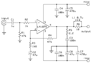
LM1875 20W Audio Power Amplifier

Description
The LM1875 is a monolithic energy firm offering very low distortions and top quality performance for consumer audio programs. The LM1875 provides 20W into a 4Ω or 8Ω fill on ±25V resources. Using an 8Ω fill and ±30V resources, over 30watts of power may be provided. The firm is designed to operate with a minimum of exterior elements. Device overburden protection is made up of both inner present limit and heat shut down. The LM1875 design uses advanced routine techniques and handling to achieve extremely low distortions amounts even at higher result energy amounts. Other excellent features include higher gain, fast number rate and a large energy bandwith, large result current move, higher present capability, and a very large supply range. The firm is inner paid for and constant for profits of 10 or greater


Schematic


PCB. solder layout

 
PCB. component layout