Tuesday, March 20, 2012

How to Read the Resistor Color Codes

Like Diode and Capasitor, Resistor is a pasive component of the electronik circuit such as in audio circuit, television and many.

Resistors "resist" the flow of electrical current. The higher the value of resistance (measured in ohms) the lower the current will be.

Resistor have color band for the value of resitance. To read color band of  the resistor, for example 10K ohm resistor with a 5% tolerance, start at the opposite side of the GOLD tolerance band and read from left to right. Write down the corresponding number from the color chart below for the 1st color band (BROWN). To the right of that number, write the corresponding number for the 2nd band (BLACK) . Now multiply that number (you should have 10) by the corresponding multiplier number of the 3rd band (ORANGE)(1000). Your answer will be 10000 or 10K. It's that easy isn't it?

If a resistor has 5 color bands, write the corresponding number of the 3rd band to the right of the 2nd before you multiply by the corresponding number of the multiplier band. If you only have 4 color bands that include a tolerance band, ignore this column and go straight to the multiplier.


Friday, March 16, 2012

Radio with LM1820 IC

LM1820 Radio
  • CA is 140 pF, 
  • CB is 60 pF, 
  • L1 has 110 and 5 turns for AM band, 
  • L2 has 98 and 12 turns for oscillator, 
  • T1 has 140 turns center tap and 2 turns, 
  • T2 has 142 turns and 7 turns, 
  • T3 has 142 turns center tap and 71 turns. 
  • IF value is 455 kHz. 
  • L3 has 3 turns on ferrite bead.

AM Radio with ZN415/ZN416

A ZN415E Radio Receiver - a amazing 12 transistors on just one nick, managing on 1.2-1.5 v.. One awesome element of this nick is that it pushes a conventional 2x32Ohm earphone immediately as one 64 Ohm cellphone. This indicates that it uses any inexpensive staying personal stereo, discman, mp3player earphone or earplug. It gets some 20-30 channels in the evening without any exterior aerial, just using the  ferrite rod. Note the attaches for the coils. I use this set to analyze the rings for my amazingly radio's as well.


1000W Power Inverter

The voltage inverter routine centered MOSFET RFP50N06. The inverter able to deal with a lot up to 1000W, it’s observed on your energy inverter transformer. The RFP50N06 Fets are ranked at 50 Amplifiers and 60 V. Heatsink is necessary to chill the MOSFETs. You may add some MOSFETs with similar relationship to get more energy. It is suggested to have a “Fuse” in the Power Range and to always have a “Load connected”, while energy is being used.

1000W power inverter Schematic

1000W power inverter Schematic PCB

Thursday, March 15, 2012

JFET Preamp By Albert Kreuzer

Schematic

PCB component side

PCB solder side
Pre amplifier with some level use JFET (BF245). This preamp can make sound like a tube preamp. Why use Jfet, cause it has like tbe caracteristc with lower overload than tube (not like tube real).

3 Channel Audio Splitter


The schematic plans of 3 channel sound splitter firm routine which designed using op-amp IC TL084. The 3 programs firm result submission is applicable just one TL084.

The very first phase is to capacitive combining having a p. 1.0 ~ electrolytic capacitor. The items are railways Vee Y2 or 4.5 V. This allows utilizing an personal 9V automobiles. A current obtain of 10 (1 M?/100 Kohm) is acquired in the first level, as well as the other three surfaces are linked as a oneness obtain current supporters. Every personal result level pushes separately through an firm result 50 pF capacitor towards the level of resistance of 5.1 k ohm fill. The reaction variety is smooth from 10 Hz to 30 kHz.

Friday, March 9, 2012

Power Amplifier 70W with STA550


Features :
  • POWER AMPLIFIER MONOCHIP BRIDGE STEREO AMPLIFIER FOR BASH® ARCHITECTURE
  • 55+55W OUTPUT POWER @ RL = 4/8 W, THD = 0.5%
  • 70+70W OUTPUT POWER @ RL = 4/8 W, THD = 10%
  • HIGH DYNAMIC PREAMPLIFIER INPUT STAGES
  • EXTERNAL PROGRAMMABLE FEEDBACK TYPE COMPRESSORS
  • AC COUPLED INPUT TO CLASS AB BRIDGE OUTPUT AMPLIFIER
  • PRECISION RECTIFIERS TO DRIVE THE DIGITAL CONVERTER
  • ON-OFF SEQUENCE/ TIMER WITH MUTE AND STANDBY
  • PROPORTIONAL OVER POWER OUTPUTCURRENT TO LIMIT THE DIGITAL CONVERTER
  • ABSOLUTE POWER BRIDGE OUTPUT TRANSISTOR POWER PROTECTION
  • ABSOLUTE OUTPUT CURRENT LIMIT
  • INTEGRATED THERMAL PROTECTION
  • POWER SUPPLY OVER VOLTAGE PROTECTION
  • FLEXIWATT POWER PACKAGE WITH 27 PIN


Schematic


Pinout

Front view

Surround Sound Decoder


The function of the routine begins up and transportation the music encompass indication quality information on the expert amount routine. This will travel the eventually left route linked with LCH Style TL072 IC1A IC1B and linked with the right route Rch. The results of these functional amps offer as the feedback shield for the next periods of the routine. IC2C is accountable for the sum of the alerts from eventually left and right to strength the center presenter result, while IC2D is accountable for increasing the stage difference between eventually left and right, which is protected in the two programs and be fed to the back sound speakers. It is necessary to ensure that the adverse devices from the back sound speakers is not based, since it will only work in similar with the main speaker


The result of the strength unit controlled IC2D takes sound to back sound speakers. This would lead to the design of sense of separating, according to the size of the room. This will integrate indication firm IC5 MN3004 sound wait that has 512 steps. From IC4 MN3101 is a time indication, which provides synchronization of IC5 as it features as an oscillator in the routine. C17 diverse capacitor handles the wait in the routine. The use of filter in the routine is to avoid the disturbance that happens during the process.


These filter can be altered to cut the wavelengths above 8 kHz and below 100 Hz, to be able to travel the back presenter. The back presenter is small and that their admittance is protected with a bandwith of 100 Hz to 8 KHz. The filter are designed around the IC6A / B is also an result shield. A potentiometer is placed on each result to aid in the modification and control of sound speakers and amps. The energy provided in the routine is 15 V and each result can travel a single strength firm.

Parts :
R1-2-7-8-12-13-18-19-20 : 47Kohm
R3-4-5-6-21-22-34-35       : 10Kohm
R9-10-11-14-15-16-17      : 15Kohm
R23-24-25-33-36               : 100ohm
R26-27-28-31-32               : 100Kohm
R29-30                                : 5.6Kohm
C1-8                                   : 47uF/25V
C2-7-9-14-23                     : 47nF
C3-6                                   : 1uF/100V

C4-5-10                             : 33pF
C11-12-15                         : 10uF/25V
C13                                    : 82nF
C16                                    : 18pF
C17                                    : 100pF mini adjustable capacitor
C18                                    : 2.2nF
C19                                    : 4.7uF/25V
C20                                    : 100nF
C21                                    : 10nF
C22                                    : 180pF
C24                                    : 150nF
RV1-RV2                           : 2 X 10Kohm  Log. pot.
RV3-4                                : 10K Log pot.
D1                                      : 1N4148
IC1-6                                 : TL072
IC2-3                                 : TL074
IC4                                    : MN3101
IC5                                    : MN3004

Wednesday, March 7, 2012

LM12 150W Simple high power amplifier

Using LM12 energy functional firm made by Nationwide Semiconductor can be built audio energy firm that can charge a highest possible energy of 150 h.
Maximum permitted heat range of the result transistors is assessed for energy limiter control routine which is part of the energetic security protection. Strength result level is not linked with that pin until the current does not surpass 14 V (± 7 V). When the nick heat range goes up above 150 ° C, result is instantly turned off.
Circuit plans indicates the use of two diodes in incorporated result that are designed to prevent the result current trip surpass the supply current when the result level is incorporated inside the contretemps and bypass the result fill is mainly inductive.

Specification
Max Out : 150W  (4Ohms) / 200W (2Ohms)
Distortion : 0.05% (4Ohms) / 0.1% (2Ohms)
Idle current : 65 - 100 mA

Notes:
L1 coil has 40 turns of enamelled copper wire 1 mm in diameter, wound on the resistance R4. It mainly uses the correct operation of the amplifier with capacitive loads reaction, such as speaker separation filters.
If using a LM12CL is advisable to use a toroidal transformer which provides in secondary 2 x 22 V (in which case the power of 150 W can be obtained only on a 2 ohm load).
Integrative be screwed on to a large thermal radiator, which should be very well insulated electrically.

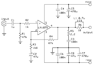
LM1875 20W Audio Power Amplifier

Description
The LM1875 is a monolithic energy firm offering very low distortions and top quality performance for consumer audio programs. The LM1875 provides 20W into a 4Ω or 8Ω fill on ±25V resources. Using an 8Ω fill and ±30V resources, over 30watts of power may be provided. The firm is designed to operate with a minimum of exterior elements. Device overburden protection is made up of both inner present limit and heat shut down. The LM1875 design uses advanced routine techniques and handling to achieve extremely low distortions amounts even at higher result energy amounts. Other excellent features include higher gain, fast number rate and a large energy bandwith, large result current move, higher present capability, and a very large supply range. The firm is inner paid for and constant for profits of 10 or greater


Schematic


PCB. solder layout

 
PCB. component layout

Tuesday, March 6, 2012

How To Clean Vinyl Records with Hand

Just as with a VPI or Nitty Gritty history washing device, the best way to fresh information is by purchasing a over the reverse available history washing remedy such as Last or Discwasher D4, which usually come with an contractor fresh. The Last Company makes fantastic washing alternatives and styling brushes for information and your stylus pen and come suggested. You could also use the same products marketed for use in devices, but you'll need to buy a good history washing fresh to use them.

To begin, lay the history on a fresh smooth working exterior such as on a smooth bath towel on a desk or position the history on the convert desk plate. If you decide to fresh your information while they are on the convert desk create sure to protected the tonearm so it doesn't unintentionally move across the history as you are washing it and do not utilize too much demand on the plate as you can harm the bearings. Also pay interest not to get any history washing fluid on the plate or convert desk complete.

Follow the guidelines on the container, but usually one is applicable the fluid to the contractor fresh and not on the history itself. Take the fresh and position it on top of the history and convert the plate counter-clockwise a few times to work the dust reduce. Look at the fresh, you should see some dust or lint on it so properly eliminate it and go another circular washing the history until no more dust or crapp seems to be on the fresh. Since liquor is the main component of most history washing alternatives the history should dry easily, but do let it air dry before tossing it over to fresh the other part or position it back in its sleeve. Before you switch the history over though create sure the exterior or plate is fresh as the filthy uncleaned part was just there!

Sunday, March 4, 2012

Echo Chamber


Resistor
R1         22K
R2, R3 4K7
R4         1K
R5         82K
R6, R13, R19 47K
R7, R12, R23, R25 120K
R8, R15, R16 100K
R9, R10 56K
R11, R12         33K
R14         15K
R17, R18         5K6
R20, R21         39K
R24, R26, R28 220k
R27, R29         10K
VR1         200K
VR2         10K Pot B
VR3         20K
VR4        100K

Capasitor
C1, C18 2n2
C2         1uF/16V
C3, C6, C7, C13 3,3uF/16V
C15, C16, C22, C23 3,3uF/16V
C4         470pF
C5         1n
C8, C9, C10 3n3
C11, C12, C20 220pF
C14         820pF
C17         1n8
C19         4n7
C21         47n
C24         100uF/16V

Semiconductor
D1         1N4148
D2         9V Zener Diode

TR1         C536

IC1, IC4 AN6651
IC2         MN3005
IC3         MN3101


Mosfet Legend Stage Amplifier by Dr. Borivoje Jagodic


Schematic


PCB Layout

Specification :


Output             :   500W RMS at 8 Ohm
                           750W RMS at 4 Ohm
THD                :  0.18 %  Max
                           0.01   at 400W
                           0.008 at 300W
Freq Respons  :  15Hz - 130 KHz
Input Voltage   :  1.55V at Output 500W 8 Ohm
                          1V      at Output 750W 4 Ohm

300W Audio Amplifier With MJ15003 and MJ15004

Power amplifier with high-pass and low-pass filter. Supplied 60V DC 35A for Stereo Consumtion, this circuit can make about 300W Power of sound. Opamp NE5534 is arranged as a differential amplifier, output of NE5534 is applied to drive stages MJE340 and MJE350 via R6 from pin 6. The output amplifier proper consists of drive stages MJE1530 and MJE1531 and Final Complementer power transistors  MJ15003 and  MJ15004, which have been arranged as symmetrical power darlingtons.


Schematic


PCB Soldering Side


PCB Component Side


Saturday, March 3, 2012

Simple Audio Video Tarnsmiter

 
Component:
R1 1 kΩ                   C1 10 µF 16V      D1 1N4007
R2 3.3 kΩ               C2 220 µF 16V     D2 1N4007
R3 1 kΩ                   C3 100 nF
U1 Aurel TX AV UHF
R4 22 kΩ
C4 10 µF 16V
U2 LM741
R5 22 kΩ         C5 1 µF 16V
R6 680 kΩ       C6 10 µF 63V
C7 1 µF 16V
C8 10 µF 16V
C9 150 pf
C10 100 nF

Thursday, March 1, 2012

Power Amp TDA 7293-dmos

PCB. Layout
PCB Layout (Component Side)


Schematic Diagram

Functions of the incorporated routine TDA7293
  •     Very higher managing current range(±50v)
  •     Dmos strength stage
  •     High result strength (100w @ thd =10%, rl = 8Ω, vs = ±40v)
  •     Muting/stand-by functions
  •     No move on/off noise
  •     Very low distortion
  •     Very low noise
  •     Shorter routine secured (with no in-put indication applied)
  •     Heat shutdown
  •     Video detector
  •     Modularity (more gadgets can be quickly linked in just like generate very low impedances)

The system is offered with both stand-by and silence features, separately pushed by two CMOS sense appropriate feedback hooks.
The tour devoted to the transferring on and off of the firm have been properly enhanced to prevent any type of out of hand sensible temporary at the result.
The series that we suggest during the ON/OFF transients.
The program of determine 5 reveals the opportunity of using only one control for both st-by and silence features. On both the hooks, the highest possible appropriate variety goes along to the managing provide current.
A little strike routine sound firm IC TDA7293

The construction is just like TDA7294, but this IC allows use resources with greater principles ​​and thus has an increased result strength can arrive at to 100 H.

To install the routine we have the recommendation of the pcb with PDF information, and information. SCh and. BRD if you need to modify this structure in Cadsoft Eagle. The red range proven in the pulling of the structure is to make the relationship using a item of cable (jumper).

Component List :
Resistors 1/8 Watt 5%
R1, R2     22K – Red, Red, Orange, Gold
R3     680 – Blue, Gray, Brown, Gold
R4     27K – Red, Violet, Orange, Gold
R5     100K – Brown, Black, Yellow, Gold
R6     33K – Orange, Orange, Orange, Gold
Capacitors
C1, C8     1000µF/63 Volts – Polarized electrolytic capacitor
C2,C9     100nF/250 Volts – Metalized polyester film capacitor
C3     1µF/250Volts – Metalized polyester film capacitor
C4, C7     22µF / 63 Volts – Polarized electrolytic capacitor
C5, C6     10µF/35 Volts – Polarized electrolytic capacitor
Semiconductors
IC1     TDA7293 – Dmos Integrated circuit audio amplifier
D1     1N4148 – Silicon diode
Miscellanea
IN     Audio input connector
OUT     Audio output connector
M/ST     Connector for connecting a mute/standby key
PW     Power supply connector
Solder, wire, printed circuit board, box, connectors, etc..

Class A Headphone Amplifier

The headphone firm was a simple routine to design. This is due to the fact that neither the fill features nor the strength demands in the result is very difficult to obtain because the earphones are generally having a 50 ohm and higher fill impedance up to 600 ohms. For the regular result, it will only require 1 V to 2 V RMS at highest possible. A category A level of firm is recommended because only low strength is necessary on this routine. Frequently, category A amps include a continuous present transistor linked from result to adverse strength and a pushed transistor linked from result to good strength. The continuous prejudice present runs immediately from the good provide to the adverse provide in the lack of feedback indication. This will result with no result present but with several capabilities absorbed.

In this routine, the transistors Q5 and Q6 should be ranked at 100 mA each, to be able to work as category A firm properly. A strength result of 1.5 H is created from the 15 V strength. A small heatsink is necessary though for each transistor. The sound feedback indication is specific by a 10K ohm logarithmic potentiometer RV1 while the result DC balanced out current for 0 V is specific by the slimmer TR1. Two tour will be required however, if it is suitable for music program.

                                                                                    Component List :
R1-4= 1.2Kohm
R2-3= 3.9Kohm
R5=100Kohm
R6-10= 10Kohm
R7-9= 2.2Kohm
R8= 150 ohm
R11-13= 6R8 ohm
R12= 4.7 ohm R14=68Kohm
RV1= 10Kohm Log. pot.
TR1= 10Kohm Trimmer
 

C1= 4.7uF 63V MKT
C2-7= 100uF 25V
C3-5= 100nF 100V MKT
C4-6= 100uF 16V
C8-10= 470uF 25V
C9-11= 100nF 100V ceramic
Q1-3= BC184
Q2-4= BC214
Q5= BD136 or BD538
Q6= BD135 or BD537
All resistors are 1/4W 1%


High Quality Pre-Amp

This is a very good preamp circuit in terms of sound quality, s / n ratio and can be used for general purposes input.

Without Tone Control?

Hmmmm .... yes for those who like HI-FI ... why should you use tone control that will only damage the authenticity of the sound reproduction.